Control & Protection Components
⚡ TeSys Motor Control
TeSys
is Schneider Electric’s global platform for motor control and protection, covering contactors, overload relays, circuit breakers, motor starters, and safety components.
It is designed to deliver reliable, modular, and coordinated motor‑starting solutions
for all industrial applications.
Your uploaded ATS130 document repeatedly references TeSys as the motor protection and switching partner for soft starters:
“ Altivar Soft Starter ATS130 can easily be integrated with the matching TeSys Deca circuit breaker… a compact soft motor starter assembled in a single block. ”
This captures TeSys’ role: the protection and switching backbone of Schneider motor control.
🔧 What TeSys Provides
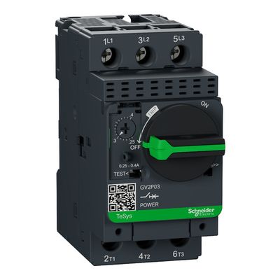
- Motor protection — thermal‑magnetic circuit breakers (GV2, GV3, GV4).
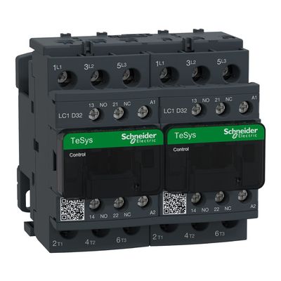
- Motor switching — TeSys D, TeSys G contactors for AC‑3/AC‑1 duty.
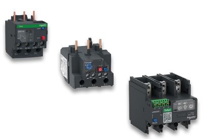
- Overload protection — LRD, LR9 relays for thermal protection.
- Complete motor starters — DOL, reversing, star‑delta, and soft‑starter combinations.
- Coordination with soft starters — tested Type 1 & Type 2 coordination with ATS130.
- EverLink terminals — vibration‑proof, maintenance‑free connections.
🧩 Key TeSys Families
- TeSys Deca — GV3/GV4 breakers + D contactors (most common).
- TeSys D — compact contactors up to 150 A.
- TeSys G — heavy‑duty contactors up to 800 A.
- TeSys LR overload relays — thermal & electronic.
- TeSys U — multifunctional motor starter (starter + breaker + relay in one).
🏭 Typical Applications
- Pumps & fans
- Compressors
- Conveyors
- Machine tools
- HVAC & building systems
- Industrial automation panels
⭐ One‑line summary
TeSys = Schneider Electric’s complete, modular, and coordinated motor control system — from protection to switching to full motor starters.